3. Modeling the Inverter
Learning objectives
In this session, you’ll learn:
- how to model a power electronics using average PWM voltages
- how to apply the d,q transform, to simplify the inverter model
3.1. Average inverter voltages
The chopped waveform of the voltage of an inverter is a faithful representation of the reality. However, representing switching events in a simulation has two disadvantages:
- it slows down the simulation considerably, because the time step of the numerical integration must be much smaller than the switching period.
- the chopped waveforms are difficult to analyze.
Therefore, it is interesting to have a second, simpler simulation model where the three-phase inverter is replaced by 3 voltage sources.
Question
Start with a copy the detailed inverter model and change it to use controlled voltage sources instead of the 6 switches.
To make the two models interchangeable, they should really have the same inputs (the 3 phase-to-ground voltages)!
Using the circuit with averaged PWM voltages, it becomes possible to write down electrical equations. However, there are still two difficulties in these equations:
- it’s a three phase circuits, with 3 inputs (inverter voltages) and 3 outputs (line currents).
- the steady state operation corresponds to a time varying regime.
To overcome these two difficulties, we will use the d,q transform.
3.2. Transforms
There are two important transforms (i.e. changes of reference frame) when dealing with the control of three phase systems (e.g. inverters and also motor drives, for the so-called “vector control” of electric machines).
- αβ (Clarke) transform: two-axis stationary reference frame → rotating vector
- dq (Park) transform: rotating reference frame → stationary vector (in sinusoidal steady state regime)
Fig. 3.1 is a visual illustration of these two reference frames.
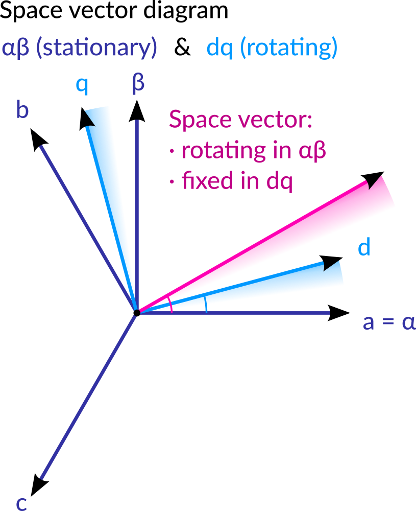
Fig. 3.1 Space vector diagram (in the αβ plane) with the basis vectors of abc (natural), αβ and dq reference frames.
Shorthand notation: \(v_{abc}\) for the column vector \((v_a, v_b, v_c)^T\), and similarly \(v_{\alpha \beta}\) and \(v_{dq}\).
3.2.1. αβ (Clarke) transform
transformation, in matrix format:
with
Question
Generate a set of balanced three phase signals.
Transform the three abc signals into the two αβ signals. Compare them (in particular the α and a components).
The vector \((v_\alpha, v_\beta)\) is sometimes called the “space vector”. What is its trajectory for a balanced signal?
Notice that this transformation drops any imbalance of the signals (sum ≠ 0). See Alpha-beta full transform to see how to handle unbalanced situations.
(Alternative approach)
We can consider the space vector as a complex number:
with complex number \(a = e^{j2\pi/3}\), i.e. a +120° rotation. The 0°, 120° and 240° oriented basis vectors are clearly visible on Fig. 3.1.
This space vector should be the same as \(v_\alpha + j v_\beta\).
3.2.2. dq (Park) transform
dq transform uses the same reference frame as the αβ transform, only rotated by an angle \(\theta\). Therefore, dq components are related to αβ components using a rotation matrix:
with \(R(\theta)\) being a rotation by angle \(-\theta\) (watch out for the signs!):
usually, angle \(\theta(t)\) is increasing at a fixed speed: \(\theta(t) = \omega t\).
Question
Apply the dq transform to the same set of balanced three phased signals.
3.3. dq inverter modeling
for dq transform, the phase of the grid voltages (phase a) is used as a reference (what does this imply for the q component of the grid voltage?). Notice that this will require a way to measure grid phase!
Question
Write the equations of the circuit in the natural abc reference frame, in a matrix form.
To make equations simpler, we can assume a balanced operation, so that we can consider that there is a 4th line connecting neutral points. In unbalanced situations, the voltage difference between the neutral points of the inverter and the grid should be taken into account (and then the full alpha-beta transform is needed).
Question
Transform the circuit equations:
- from the abc frame to the αβ frame (very easy !)
- from the αβ frame to the dq frame (less easy)
Danger
One of the difficulty of applying the αβ→dq transform is that the rotation matrix is time varying. Therefore, you should compute first the derivative of the rotation matrix!
3.3.1. dq block diagram
Using the dq differential equations of the circuit, make a block diagram of the system, using:
- the inverter voltages as inputs (d and q components)
- the lines currents as outputs (d and q components).
It is important to notice that d and q channels are coupled (unlike abc or αβ channels).
Question
To underline the importance of the cross coupling terms, compute the steady-state V_inv → I gain (this gain is a 2x2 matrix).
You should relate this result to the single phase AC circuit analysis of section Preamble: AC Power transmission.
With such a simplified model, where variables are constant in steady-state, it becomes much easier to setup a control scheme, like a classical PI control. This is the topic of the next session.