1. Context & Objectives
1.1. Technical context
Historically, power plants (thermal power plants, hydroelectric dams, …) were connected directly to the electrical grid. Indeed, electric generators used in these plants (synchronous or induction machines) are meant to be connected directly to a three-phase power system. Only a transformer may be used as an interface to match voltage levels between the machine and the grid.
Since the late 20th century, with the development of renewable (solar and wind) power generation, there are more and more power generators that are connected indirectly to the grid, using a power electronics converter as an interface. This is particularly true for solar photovoltaics (PV) systems, where a converter is required to reshape the direct current (DC) produced by the PV cells into an alternating current (AC) at a suitable frequency (often 50 Hz or 60 Hz) that can be fed into the grid.
A device that transfer energy from DC source to an AC source is called an inverter. Grid connected inverters brings a lot of flexibility in terms of power transfer, because the power flows (active and reactive power) can be controlled precisely. It this power flow control that we want to study in this lab course.
Grid connected inverters can also provide other services to the grid, like power quality improvement (e.g. reducing the harmonic distortion), but these are not covered in this lab.
1.1.1. The importance of controlling power flows
Question
By the way, why is it important to control active and reactive power flows on an electricity grid ?
1.2. Learning objectives
Objective of this series of lab sessions
Being able to understand the structure, design and test the control of the power flows of a three-phase grid connected inverter.
This also means you’ll have to understand the operation and the modeling of the inverter.
1.2.1. System under study
In this course, we will consider a three-phase rooftop PV system with an apparent power of 20 kVA (see as an example the Sunny Tripower inverter by the German manufacturer SMA). Such a system could be installed on a small commercial building using 70 typical 300 W modules of about 1.5 m² (see for example PV modules by Suntech, a large manufacter based in Wuxi, China).
Note that we will focus on the operation of the grid connected converter, which is used in other systems (wind generation, motor drives). As a consequence, we will not cover the details of the solar power conversion. In particular, we will not cover the typical issue of MPPT, which is performed using additional DC-DC converters. Instead, we will use a fixed voltage source as a (simplistic) model for the PV panels.
1.2.2. Prerequisites
This course requires that you are already familiar with:
- Modeling an electrical circuit
- in the time domain (differential equations),
- in complex plane (phasor equations) and
- in the Laplace domain (transfer functions)
- Pulse Width Modulation (PWM) operation of a simple power electronics converter (e.g. a buck or a boost DC-DC converter).
- Assessing the stability of a closed loop system given its open loop frequency response. This include finding the phase margin on a Bode or Nyquist diagram.
- Tuning a PI controller so that the performance of the closed loop system matches a given performance level (settling time, overshoot).
1.2.3. Transversal skill: choosing appropriate models
Because the inverter is a quite complex system, several models will be made, with varying levels of complexity (and corresponding level of details ). Fig. 1.1 illustrates how, starting with a high fidelity model (switched model) we will go down to a very simplified model (DC model). With such a simplified model, an appropriate control can be designed using standard tools for linear control. Finally, the control scheme will be tested against models of increasing complexity.
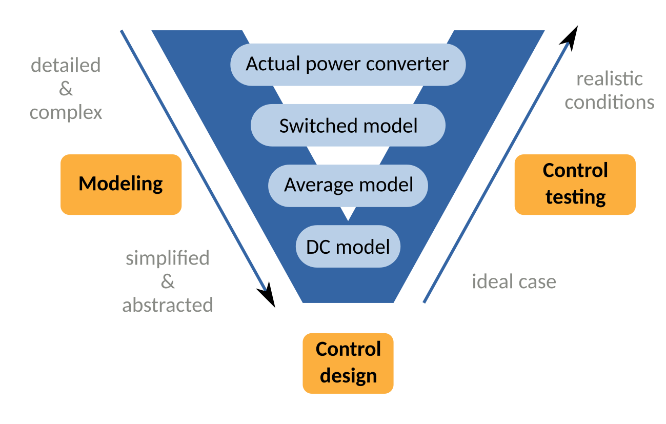
Fig. 1.1 “V model” approach to design the control of a power electronics converter.
At the end of this lab, you will have practiced an important transversal skill: the ability to choose a model of appriopriate complexity/level of detail for a given task. Or like in this lab, go as far as switch between different models at different stages of the design process.