3. Voltage control with reactive power¶
The injection/absorbtion of reactive power influences the voltage magnitude. For this reason, it possible to adjust reactive power to keep the voltage closer to its nominal value: 1 pu ± 5%.
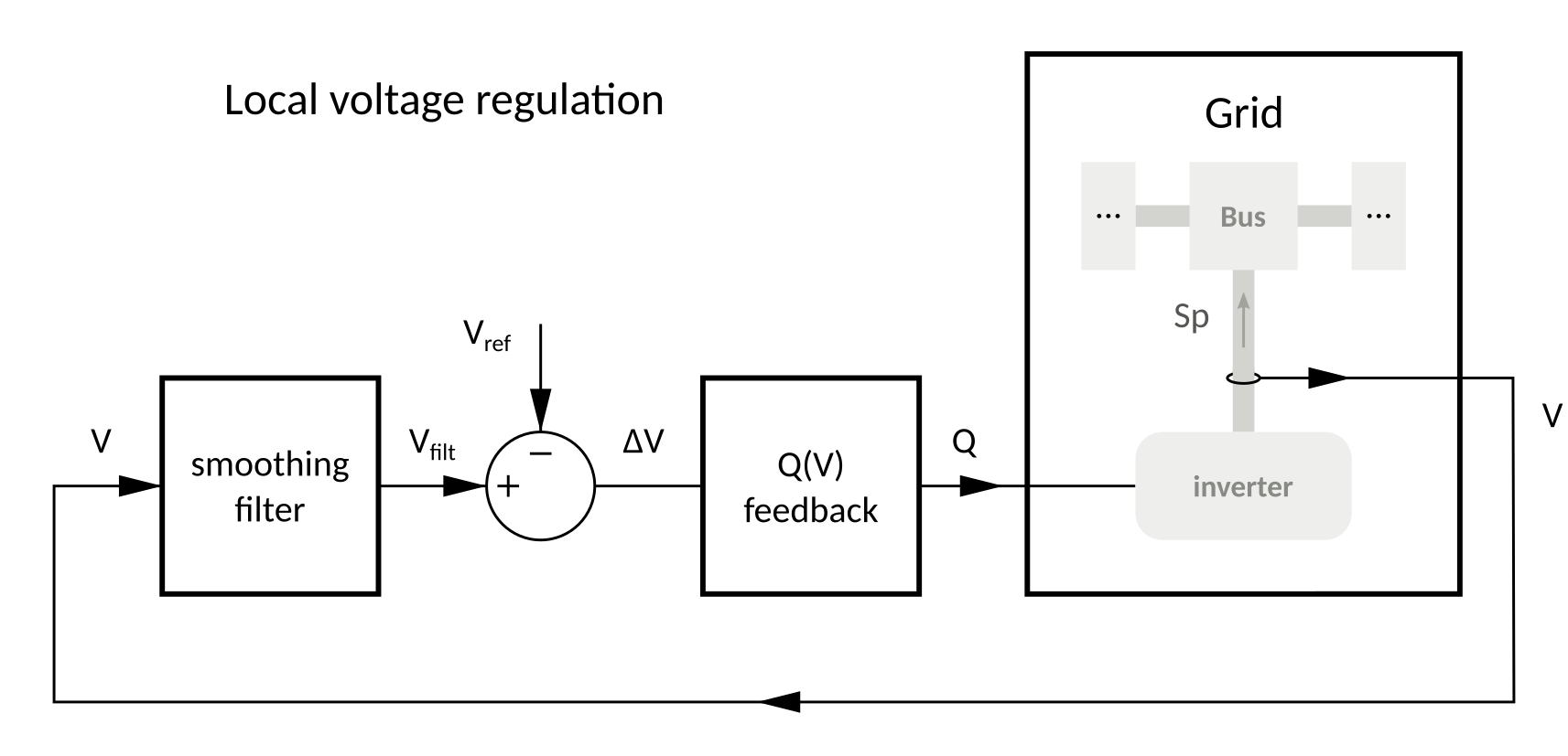
Presently, operators of distribution grid (DSOs) only require energy producer to inject a fixed amount of reactive power (in fact, a fixed tan phi = Q/P), but there is a reflection to include feedback control to adjust Q based on voltage measurement. The structure is shown on Fig. 3.1.

Fig. 3.1 Decentralized voltage control using reactive power injection by each energy producer, based on local voltage measurement.
If the indroduction of such a voltage feedback is expected to improve the grid operation, it also bears the risk to generate oscillation or even instability (as every closed loop system). The goal of this section is to study the tuning of a linear feedback to reach acceptable performance.
3.1. Effect of reactive power injection¶
The power flow routine developed previously (cf. section Power flow) gives us a numerical black-box model of the grid. It can thus be used to study numerically the effect of Q injection on the voltage. However, such a blackbox model cannot be used in the analysis of a feedback control. A simpler model is required…
3.1.1. Numerical analysis¶
Use the power flow routine in a series of experiment to see the effect of injecting reactive power on the test grid (both on node 2 and node 3).
Plot the result in a meaningful way.
For wich range of reactive power the voltage variation can be considered linear?
3.1.2. Numerical linear approximation¶
Derive a linear (or more precisely affine) model (gain matrix) for the effect of Q injections on the voltage magnitudes:
Here notation \(\underline{V}\) means the vector of voltage magnitudes at each bus (not a complex value). \(\underline{V}_0\) is the voltage magnitude at the linearization point \(\underline{Q}_0\): \(\underline{V}_0 = V(\underline{Q}_0)\), computed from the power flow model.
self check: the gain matrix (when working in pu):
K = 1e-2 *

   0.88   1.03
   0.92   2.17
References: Wikipedia page on finite difference to recall left (backward), right (forward) and central differences.
3.1.3. Analytical linear approximation¶
Based on the power flow equations, is it possible to derive an analytical formula for the linear sensitivity ? (simplifying assumptions may be needed).
3.2. Decentralized control with Q(U) feedback¶
Each producer is now asked to inject reactive power proportional to the voltage (the deviation from the nominal value).
where \(c\) is the gain of the feedback controler (should be negative!).
\(V_{filt}\) is the filtered measurement of the voltage. To start with, the filter is just a delay of one sampling period:
3.2.1. Smoothing filter¶
voltage measurement is smoothed to reject fast fluctuations and also to get better stability.
First order autoregressive filter (“exponential smoothing”):
where \(a \in [0,1]\) is the tuning parameter of the filter:
- for \(a\) close to zero, there is no smoothing (just the measurement delay of one sampling period)
- the closer to one \(a\) is, the more fluctuations are smoothed out. However, too much smoothing slows down the regulation
Compare simulations with different values of a: 0, 0.5, 0.9, 0.99…
3.2.2. Analytical analysis¶
Write the state space equation of the control (you can start with one producer).
Using the linearized model of the network, derive an analytical criterion for stability (tip: use the condition on eignenvalues of the “A” matrix).
Also, derive the relation between control feedback and:
- steady state error \(V_{filt}(k) - V_{ref}\)
- steady state Q injection (we want the energy producer to keep a reasonable power factor)
Test case for c = -200:
- which filter setting makes the system stable ?
- which filter setting makes the system converge fast (again using eignenvalues) ?
Check the validity of the criterion with simulations.
Check the validity of the steady state opterating point.
3.3. Centralized control with Optimal Power Flow¶
The decentralized linear feedback is compared with a centralized optimization.
Objective: minimize network losses, which is equivalent to minimize the active power production.
runopf Matpower command (§6 [MATPOWER-man])